
I work as an R&D engineer for a defense company. Lots of fun toys at work.
Have you tried using Shapeways? https://www.shapeways.com If you ever need a part that you can't seem to get right on your home printer, they can provide a much larger array of materials and finishes. (Including gold plating...so maybe a printed gold IMSB ?)
Optimizing Danmar M6 2 Post Lift
-
sweet victory
- OG (First 100 Outposters!)
- Posts: 616
- Joined: Mon Jan 29, 2018 12:55 pm
-
sweet victory
- OG (First 100 Outposters!)
- Posts: 616
- Joined: Mon Jan 29, 2018 12:55 pm
Re: Optimizing Danmar M6 2 Post Lift
I'm really not interested in pursuing a patent for this. Just thought it would be a practical project to share with you guys. Once I settle on a design, I'm more than happy to share the STL file on thingiverse. Time is scarce, but if guys are interested I can probably make a few extras.gnat wrote: ↑Wed Feb 06, 2019 8:01 am You can patent anything that isn't already patented or has prior art.
You might lose on a challenge, but it's not really costly to file the patent.
If you start selling it and it becomes popular, however, expect some shop in China to not give a shit about our patent law and undercut you with a cheap knock off that may or may not kill someone when their welded aluminum pipe collapses...
I vote that you put the design info up somewhere like Thingverse and (if you are interested) produce sets in small quantities for a reasonable price (material, power, time, and beer) for those interested.
-
Einsteiger

- He's Back and He's Angry
- Posts: 462
- Joined: Sun Sep 30, 2018 11:40 am
- Location: Overland Park KS
Re: Optimizing Danmar M6 2 Post Lift
Good plan. Producing any kind of product brings with it the specter of the dreaded "product liability". Insurance alone can get expensive.
Kevin
1999 C2 - Vesuvio Metallic
OP Kansas
1999 C2 - Vesuvio Metallic
OP Kansas
-
sweet victory
- OG (First 100 Outposters!)
- Posts: 616
- Joined: Mon Jan 29, 2018 12:55 pm
Re: Optimizing Danmar M6 2 Post Lift
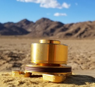
Here is the shortened version next to the originals.

I'll try to better illustrate my goal here. I want to be able to line up the pad perfectly, every single time, to create a repeatable processes that requires minimal effort. As an R&D engineer, I don't just design products, I design processes.
You can visually locate the lift pad under the lift point using the peg and slot.

You confirm the lift pad is directly under the lift point by sliding the lift pad upwards.

I think I will tweak the design one more time. As you can see, it rubs the bottom of the lift point. I will shave off ~.20" or so. Also, I'm thinking that I will taper the peg instead having it straight with a chamfer. I think it will locate itself a bit easier in case there is a little movement when the arms are lifted.
I'll try to better illustrate my goal here. I want to be able to line up the pad perfectly, every single time, to create a repeatable processes that requires minimal effort. As an R&D engineer, I don't just design products, I design processes.
You can visually locate the lift pad under the lift point using the peg and slot.
You confirm the lift pad is directly under the lift point by sliding the lift pad upwards.
I think I will tweak the design one more time. As you can see, it rubs the bottom of the lift point. I will shave off ~.20" or so. Also, I'm thinking that I will taper the peg instead having it straight with a chamfer. I think it will locate itself a bit easier in case there is a little movement when the arms are lifted.
Re: Optimizing Danmar M6 2 Post Lift
Sadly so many (especially in the car industry) don't think this way which is how we end up with absolutely brain dead designs that then make usability and servicing a nightmare.sweet victory wrote: ↑Wed Feb 06, 2019 6:22 pm I'll try to better illustrate my goal here. I want to be able to line up the pad perfectly, every single time, to create a repeatable processes that requires minimal effort. As an R&D engineer, I don't just design products, I design processes.
Good on you!
Such an elegantly simple solution to an annoying problem. I wondered what the sculpting on the sides was about as I figured it was more than decorative. Some knurling on the final product probably wouldn't be amiss to help with hands/gloves that might have oil or grease on them. Getting a finger pinched by one slipping from your hand with what I imagine the final weight will be would not make for a pleasant weekend afternoon working on the carYou confirm the lift pad is directly under the lift point by sliding the lift pad upwards.
-
Einsteiger
- He's Back and He's Angry
- Posts: 462
- Joined: Sun Sep 30, 2018 11:40 am
- Location: Overland Park KS
Re: Optimizing Danmar M6 2 Post Lift
Round peg, round hole. Simplicity.
- Attachments
-
- excellent.gif (478.67 KiB) Viewed 8674 times
Kevin
1999 C2 - Vesuvio Metallic
OP Kansas
1999 C2 - Vesuvio Metallic
OP Kansas
-
sweet victory
- OG (First 100 Outposters!)
- Posts: 616
- Joined: Mon Jan 29, 2018 12:55 pm
Re: Optimizing Danmar M6 2 Post Lift
Yeah, not sure how a lot of things get through design review meetings without being scrutinized. I'm glad the work I do isn't constrained by "value engineering" (making shit cheap as possible). Quiet the opposite with the DoD...gnat wrote: ↑Wed Feb 06, 2019 6:38 pm Sadly so many (especially in the car industry) don't think this way which is how we end up with absolutely brain dead designs that then make usability and servicing a nightmare.
Good on you!
Such an elegantly simple solution to an annoying problem. I wondered what the sculpting on the sides was about as I figured it was more than decorative. Some knurling on the final product probably wouldn't be amiss to help with hands/gloves that might have oil or grease on them. Getting a finger pinched by one slipping from your hand with what I imagine the final weight will be would not make for a pleasant weekend afternoon working on the car
There's elegance in simplicity. I don't think we have a knurling tool that can knurl that concave feature. It will be turned from 6061 or 1018 and will only be about 3.13" overall length, so it will be quiet light.
-
sweet victory
- OG (First 100 Outposters!)
- Posts: 616
- Joined: Mon Jan 29, 2018 12:55 pm
Re: Optimizing Danmar M6 2 Post Lift
Thank god I was awake in class that day in kindergarten...
-
Dgi 07

- OG (First 100 Outposters!)
- Posts: 218
- Joined: Mon Jan 29, 2018 7:30 am
- Location: People's Republic of New Jersey
Re: Optimizing Danmar M6 2 Post Lift
Seems like you spend a lot of time adjusting the lift arms.sweet victory wrote: ↑Tue Feb 05, 2019 6:31 pm
- Position arms under car
- Crawl around and place hockey pucks
- Lift arms a few inches
- Crawl around each corner for placement check
- Lower arms
- Crawl around each other to adjust
- lift arms a few inches
- Crawl around each corner for placement check
- Lift car to desired height
Tip from a mechanic. Use the rings on the base of the lift and pull up on them . This allows you to move the arm, without putting it back down to adjust.
Cuts your adjustment time in half.
-
sweet victory
- OG (First 100 Outposters!)
- Posts: 616
- Joined: Mon Jan 29, 2018 12:55 pm
Re: Optimizing Danmar M6 2 Post Lift
I cannot just place the hockey pad on the lift and push it under the vehicle. I have to push the arm under the car, and then try to center the hockey puck. (Only on the rear since the side skirt sits lower) It's very difficult to see how the car is sitting on the hockey puck unless I raise the vehicle a few inches, and that's why it takes so much time. I don't adjust every corner, usually just one of the rears. I still appreciate the help.
I'm not expecting to have to make any adjustments after I get these new lift pads made.